

Orion Reentry: The Engineering Physics Behind the Most Dangerous Eight Minutes in Human Spaceflight
A deep technical examination of ablative thermal protection, skip-entry mechanics, pyrolysis gas dynamics, and the structural margin decisions that brought four astronauts home from the Moon.
On the evening of April 10, 2026, four astronauts aboard the Orion spacecraft — Commander Reid Wiseman, Pilot Victor Glover, and Mission Specialists Christina Koch and Jeremy Hansen — reentered Earth’s atmosphere at approximately 24,000 mph (~Mach 32), completing the first crewed lunar mission since Apollo 17 in 1972. What followed over the next eight minutes was one of the most precisely engineered sequences in aerospace: a controlled thermal, aerodynamic, and structural event operating at the absolute limits of material science, with no redundancy and no abort option.
There is no redundancy for the thermal protection system. The heat shield must work.
This is not dramatic language. It is an accurate engineering statement. Unlike propulsion, communications, or power systems — all of which carry redundant paths — the Orion heat shield is a single-string system. If it fails, the crew module burns. Understanding why it has worked, why it partially failed on Artemis I, and what NASA traded to make Artemis II survivable is one of the most instructive multiphysics case studies in modern aerospace engineering.
The Environment: What Mach 32 Actually Means Structurally
At lunar return velocity, the Orion capsule encounters an aerothermodynamic environment qualitatively different from low Earth orbit reentry. The kinetic energy is approximately 2.4× higher than a Soyuz or Crew Dragon returning from ISS. That delta is not linear in its structural implications — it is exponential in heat flux.
Orion Artemis II — Reentry Design Envelope
At these velocities, the air ahead of the capsule cannot move out of the way fast enough. It compresses and heats not through friction in the classical sense, but through shock-layer compression and radiation. At Mach 32, radiative heating — energy emitted directly from the hot plasma shock layer to the vehicle surface — contributes a significant fraction of total heat flux, unlike at Mach 25 (ISS return) where convective heating dominates. This is why lunar-return TPS design is substantially more demanding than ISS-return TPS design, even though the speed difference appears modest in absolute terms.
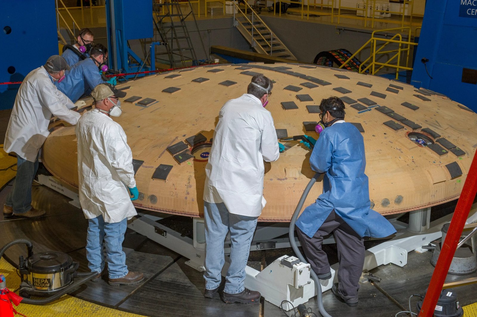
Avcoat: The Material Physics of Ablation
The Orion heat shield uses Avcoat, a low-density, silica-fiber-reinforced ablative material with an epoxy novolac resin matrix. It is conceptually descended from the Apollo-era heat shield material, but reformulated in the 2010s for the Orion program — a reformulation that, as Artemis I demonstrated, altered its permeability characteristics in ways that were not fully characterized before flight.
Ablative TPS works through a sequence of thermochemical processes rather than passive insulation:
As surface temperatures rise, the organic resin matrix decomposes endothermically. The thermal energy driving decomposition is drawn from the incoming heat flux, absorbing energy that would otherwise conduct inward to the structure. Pyrolysis gases are generated in this zone.
The decomposed resin leaves behind a carbonaceous char layer — a porous, low-thermal-conductivity solid that acts as a secondary insulator and a substrate for surface chemistry reactions. Char quality is critical: it must remain mechanically coherent under the combined aerodynamic shear and thermal gradient.
The char layer ablates — it oxidizes, sublimes, and mechanically erodes — carrying thermal energy away from the vehicle. Controlled, gradual recession is the design intent. Spallation — large fragment loss — is a failure mode.
Pyrolysis gases migrate outward through the porous char layer and enter the boundary layer, providing a blowing effect that reduces convective heating. This transpiration cooling mechanism depends critically on material permeability — the central parameter implicated in the Artemis I damage.
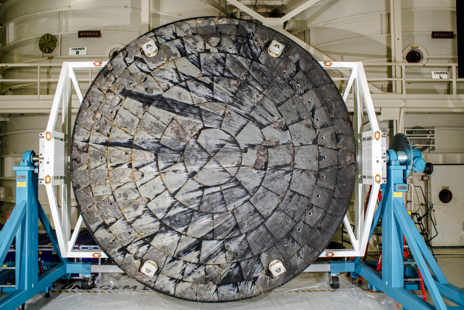
The Artemis I Damage: A Coupled Multiphysics Failure Mode
Post-flight inspection of the Artemis I heat shield revealed material loss in over 100 discrete locations — significantly greater than pre-flight predictions. After nearly two years of analysis, NASA’s conclusion identified the following failure sequence, centered on the skip-entry trajectory profile:
The Artemis I reentry used a skip trajectory: the capsule dipped into the upper atmosphere, decelerated partially, then briefly exited before making a second atmospheric entry. This double-pulse thermal loading created a sequence that standard single-pass ablation models did not fully capture.
The root cause was not the material itself, but the interaction between material permeability, thermal gradient reversal during coast, and trapped pyrolysis gas pressure — a coupled problem that existing models had not bounded.
During the coast phase between atmospheric passes, the outer char layer began to cool while inner pyrolysis zones remained hot. Pyrolysis gases generated in the subsurface zone could not transpire outward fast enough through the partially cooled, reduced-permeability char. Pressure built up beneath the char layer. When the capsule re-entered for the second pass, the combined thermal and gas pressure load exceeded the mechanical strength of the char bond, causing spallation — brittle fracture and ejection of char fragments.
This is a problem in four coupled physics domains simultaneously: heat transfer, chemical decomposition kinetics, porous media gas flow, and structural mechanics under transient load. Each domain is individually well-understood. Their interaction under the specific skip-entry thermal history was not.
Entry Profile Comparison: Artemis I vs. Artemis II
| Parameter | Artemis I — Skip Entry | Artemis II — Lofted Direct |
|---|---|---|
| Entry Profile | Two-pulse skip trajectory | Single lofted profile |
| Peak Heat Flux | Lower instantaneous | Higher instantaneous |
| Thermal Cycling | High — coast phase reversal | Reduced — monotonic loading |
| Pyrolysis Gas Pressure Risk | Higher — trapped gas buildup | Lower — continuous transpiration |
| Char Permeability | Reduced during coast cooling | Maintained through continuous heating |
| Splashdown Accuracy | Wider range capability | Reduced weather avoidance range |
| TPS Damage Observed | 100+ spallation sites | Under post-flight evaluation |
The Engineering Trade: Accepting Higher Peak Loads to Eliminate Complex Failure Modes
NASA’s decision for Artemis II was not a redesign. It was a trajectory trade: eliminate the skip coast phase, accept higher instantaneous peak heat flux, and maintain char permeability through continuous monotonic thermal loading. The logic is thermomechanically sound — a single heating pulse through a permeable char layer is a well-characterized problem. A two-pulse cycle with thermal gradient reversal and trapped gas dynamics is not.
This represents a classic margin trade that experienced structures engineers will recognize: when you cannot fully characterize a complex failure mode, simplify the loading environment. The Artemis II lofted profile does produce higher peak surface temperatures, but it trades a bounded, well-understood ablation problem for an unbounded, coupled multiphysics one.
Former NASA Chief Technologist Charles Camarda publicly raised concerns that the full physics of the Artemis I damage mechanism had not been completely bounded prior to the Artemis II crewed flight — specifically that thermal gradient coupling, gas permeability interactions, and transient multiphysics behavior may not be fully captured in current validated models. NASA’s position, supported by wind tunnel, laser, and hypervelocity testing, is that the root cause was identified and the trajectory modification is sufficient to mitigate recurrence. The structural margin assessment indicates that even with localized TPS degradation, the underlying titanium substrate and composite pressure vessel remain within allowable limits.
The Final Eight Minutes: Sequence of Events
Orion enters the sensible atmosphere heat-shield-forward at ~24,000 mph. Aerodynamic forces begin building. Crew oriented aft-facing.
Peak convective and radiative heat flux. Surface temperature reaches ~2,700°C. Avcoat pyrolysis and char formation at maximum rate. Plasma sheath forms — radio blackout begins.
Ionized plasma sheath surrounding the capsule absorbs and reflects radio frequency signals. No communication with crew. Ground teams monitor pre-blackout telemetry and await signal reacquisition.
Maximum aerodynamic deceleration load on crew and structure. Crew restrained in pressure suits. Structural loads on heat shield attachment, forward bay, and pressure vessel at design maximum.
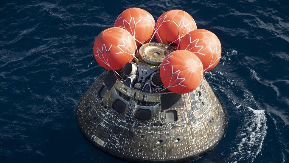
Two 23-ft diameter drogue chutes stabilize capsule attitude. Velocity reduced to ~130 mph. Forward bay cover jettisoned pyrotechnically to expose main chute pack.
Three 116-ft diameter main parachutes deployed in reefed stages to control opening load. Velocity reduced progressively to ~17 mph at splashdown.
April 10, 2026, 8:07 PM EDT. Recovery by USS John P. Murtha (LPD-26). Immediate post-splashdown heat shield photography by Navy divers before crew extraction.
What Artemis II Teaches the Next Generation of Aerospace Engineers
1. Multiphysics coupling creates failure modes that single-discipline analysis cannot predict. The Artemis I TPS damage was not a material failure, a structural failure, or a thermal failure in isolation. It was the interaction of all three under a specific transient loading history. No single engineering discipline owns that problem. It requires integrated systems thinking across thermal, structural, and fluid disciplines simultaneously.
2. Trajectory is a design variable for structural integrity. Most engineers think of trajectory as a performance or navigation parameter. Artemis II demonstrates that trajectory directly drives the structural loading environment of the TPS. The engineering team treated flight path angle, skip geometry, and thermal cycling as structural design inputs — and changed them to fix a materials problem. This is sophisticated systems-level engineering.
3. Ground testing cannot fully replicate flight. NASA conducted wind tunnel testing, laser heating tests, and hypervelocity arc-jet testing on Avcoat samples. None of these facilities could reproduce the exact coupled thermal history of a skip reentry at lunar return velocity. The test-analysis correlation problem for ablative TPS under multi-pulse loading is still an open research area. Artemis I was, in a very real sense, the highest-fidelity test that could ever be run — and it produced data that changed the mission architecture.
4. Margins are not a buffer — they are the engineering argument. The Artemis II “fly as is” decision was not recklessness. It was a margin-based structural argument: even with partial TPS degradation consistent with Artemis I, the thermal soak-through to the aluminum and composite substructure remains within allowable limits. That argument requires not just analysis, but demonstrated correlation between post-flight damage and internal temperature measurements. That data existed from Artemis I, and it provided the margin basis for Artemis II crew certification.
Reentry is one of the few phases in aerospace where modeling is still imperfect, testing is limited, and margins are everything. There is no redundancy. No second chance. Just physics, engineering judgment, and execution. On April 10, 2026, the execution held.
Ready to Enroll?
NovaEd AeroLab — Spring II Classes Now Open
Aerospace STEM enrichment for kids Grades 1–8, taught by a working senior aerospace engineer with 30+ years of experience including human spaceflight. Real engineering. Real flight. Real fun.
📍 Orange
Starting Wed Apr 8
Level 1A Gr 1–3 · Wed 4:00–5:30
Level 2A Gr 4–7 · Wed 5:30–7:00
Level 3A Gr 8+ · Wed 7:00–8:30
📍 Corona
Starting Thu Apr 10
Level 1A Gr 1–3 · Thu 4:00–5:30
Level 2A Gr 4–7 · Thu 5:30–7:00
Level 3A Gr 8+ · Mon 5:30–7:00
Level 1C Gr 1–5 · Mon 4:00–5:30 ✦
Level 2C Gr 5+ · Mon 5:30–7:00
📍 Fontana
Starting Fri Apr 11
Level 1A Gr 1–3 · Fri 2:30–4:00
Level 2A Gr 4–7 · Fri 4:00–5:30