

Advanced Composite Materials in Modern Aerospace
From Carbon Fiber Aircraft Structures to Ultra‑High Temperature Spacecraft Materials
A deep technical review of the composite material systems enabling modern aerospace — from CFRP primary structure to CMC hot sections, RCC leading edges, and next-generation UHTC hypersonic materials.
Over the past several decades, aerospace engineering has undergone a transformation driven by a single underlying force: the inadequacy of metals for the environments modern vehicles must survive. Aluminum fails thermally at Mach 3. Steel is too heavy for orbital mass fractions. Titanium is expensive and difficult to manufacture at scale. The response — across aircraft, spacecraft, hypersonic vehicles, and propulsion systems — has been the progressive displacement of monolithic metals by engineered composite material systems, each tailored to a specific combination of structural, thermal, and environmental demands.
Composite materials are no longer simply replacing metals in aerospace structures — they are enabling entirely new vehicle architectures that would be physically impossible in aluminum or steel.
The material selection problem in aerospace is fundamentally a multi-objective optimization across specific strength, specific stiffness, maximum use temperature, oxidation resistance, damage tolerance, manufacturability, and cost. No single material wins all categories. What follows is a systematic technical review of the major composite systems deployed today, organized by their thermal operating regime — from ambient-temperature primary structure through the extreme environments of atmospheric reentry.
Carbon Fiber Reinforced Polymer (CFRP): The Structural Workhorse
CFRP — carbon fibers embedded in a polymer matrix, typically epoxy, BMI, or cyanate ester — is the dominant structural composite in modern aerospace. Its appeal is straightforward: specific strength (strength divided by density) and specific stiffness (modulus divided by density) that exceed aluminum alloys by factors of 3–5×, combined with excellent fatigue resistance and zero corrosion susceptibility.
The critical structural parameter driving CFRP adoption in primary structure is laminate tailoring: by stacking unidirectional prepreg plies at engineered orientations (0°, ±45°, 90°), designers can direct stiffness and strength precisely along load paths — something impossible in isotropic metals. A fuselage barrel in tension requires different laminate architecture than a wing cover in combined bending and shear. This directional design freedom is the deepest structural advantage of CFRP over aluminum.
Major CFRP Aircraft Programs
| Aircraft | Composite Fraction | Primary CFRP Applications | Matrix System |
|---|---|---|---|
| Boeing 787 | ~50% by weight | One-piece fuselage barrels, wings, empennage | Epoxy prepreg |
| Airbus A350 | ~53% by weight | Fuselage panels, full composite wing box | Epoxy prepreg |
| F-35 Lightning II | ~35% by weight | Fuselage skins, control surfaces, inlet | BMI (high-temp) |
| Beechcraft Starship | ~100% airframe | First large all-composite certified aircraft | Epoxy |
CFRP’s limitation is thermally fundamental: polymer matrices begin to soften and degrade above approximately 150–180°C for standard epoxy systems. This makes standard CFRP inadequate for engine hot sections, supersonic leading edges, or any structure in sustained hypersonic flow. The moment aerodynamic heating exceeds these temperatures, the material selection problem requires an entirely different class of composite.
High-Temperature Polymer Matrix Composites: Extending the Thermal Ceiling
To push the thermal boundary of polymer composites without transitioning to ceramics, aerospace engineers developed advanced resin systems that trade processability for elevated service temperature:
Bismaleimide (BMI) resins offer service temperatures of ~200–230°C and are used extensively in military aircraft structures and engine nacelles. The F-35’s composite content relies heavily on BMI rather than epoxy due to the elevated temperatures around the engine bay.
Cyanate ester resins push the ceiling further to ~250–300°C with lower moisture absorption than BMI, making them attractive for spacecraft panels and fairings where dimensional stability under thermal cycling matters.
PEEK and other thermoplastic matrices offer a different trade: they can be reprocessed (welded, remolded), which enables novel joining strategies and out-of-autoclave manufacturing, and maintain structural capability to ~250°C continuously.
These systems bridge the gap between standard CFRP and ceramic matrix composites — but their upper thermal limit (~300°C) still falls orders of magnitude short of hypersonic structural environments.
Ceramic Matrix Composites (CMC): Entering the High-Temperature Regime
Above ~1,000°C, polymer matrices are not merely degraded — they do not exist. Ceramic Matrix Composites replace both fiber and matrix with ceramic constituents, enabling structural capability in environments that destroy any polymer-based system.
The two dominant CMC systems in current aerospace application are C/SiC (carbon fiber reinforced silicon carbide) and SiC/SiC (silicon carbide fiber in a silicon carbide matrix). SiC/SiC has become the system of choice for oxidizing environments because carbon fibers oxidize above ~400°C, while SiC fibers maintain oxidation resistance to ~1,400°C.
CMC’s structural liability is brittleness. Unlike metals, which plastically deform before fracture (providing warning and energy absorption), ceramics fail in a brittle mode with little prior deformation. The role of the ceramic fiber reinforcement is specifically to introduce crack deflection mechanisms — forcing cracks to travel around fibers rather than through them, improving fracture toughness and producing pseudo-ductile behavior in the stress-strain curve. This is the fundamental materials engineering challenge of CMC design: maintaining high-temperature capability while building in enough damage tolerance for structural certification.
Reinforced Carbon-Carbon (RCC): The Extreme End of the Spectrum
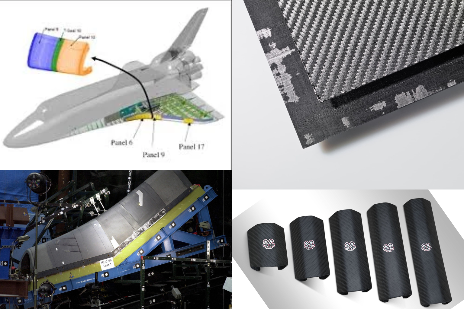
RCC is carbon fiber reinforced by a carbon matrix — effectively an all-carbon composite. It can withstand temperatures exceeding 2,000°C and has exceptional thermal shock resistance and low thermal expansion, making it dimensionally stable through extreme heating cycles. It was the material of choice for the Space Shuttle’s wing leading edges and nose cap — the highest-temperature regions during reentry.
RCC’s critical limitation is oxidation. Carbon oxidizes readily in air above ~400°C, converting to CO₂ and destroying the material. The Shuttle’s RCC panels required a silicon carbide oxidation protection coating — and it was a breach of that coating on Columbia’s left wing leading edge, caused by foam impact during launch, that allowed plasma to enter the wing structure during STS-107 reentry in February 2003, with catastrophic results. The Columbia accident is the definitive case study in why composite structural integrity, damage tolerance inspection, and material vulnerability assessment are life-critical disciplines in human spaceflight.
Ablative Composite Heat Shields: Designed to Be Consumed
Ablative TPS represents a fundamentally different engineering philosophy from structural composites. Rather than maintaining structural integrity through thermal exposure, ablative materials are designed to sacrifice themselves — absorbing heat through endothermic pyrolysis reactions and carrying energy away from the vehicle via controlled material loss.
The most well-known ablative system in current use is Avcoat — silica fibers embedded in an epoxy novolac resin matrix within a fiberglass honeycomb carrier structure. Used on the Apollo Command Module and the NASA Orion spacecraft, Avcoat’s ablation sequence involves resin pyrolysis, char formation, and gas transpiration through the porous char layer. As detailed in the companion Orion reentry article, the interaction between material permeability, multi-pulse thermal loading, and pyrolysis gas pressure was the root cause of the Artemis I heat shield damage — a coupled multiphysics problem that Avcoat’s single-pulse design heritage did not anticipate.
Ablative systems trade reusability for reliability. They are single-use — requiring full replacement or refurbishment after each flight — but their performance envelope under very high heat flux with no active cooling is unmatched by any other TPS approach at current technology readiness levels.
Fiber Architecture and Manufacturing: Where Material Becomes Structure
Material system selection defines the thermal and mechanical capability envelope. But the realized structural performance of any composite component depends equally on fiber architecture — how fibers are arranged in three-dimensional space — and manufacturing process — how that architecture is achieved and consolidated.
Most aircraft primary structure uses unidirectional prepreg layup: plies of fibers aligned in a single direction, stacked at engineered orientations (0°, ±45°, 90°) and cured under autoclave pressure and temperature. This produces the highest fiber volume fractions (~55–65%) and best in-plane properties, but is labor-intensive and sensitive to ply drop-off and interlaminar stress concentrations.
High-temperature CMC and RCC structures typically use woven or braided fiber architectures — 2D woven cloth or 3D woven preforms — which provide through-thickness reinforcement and dramatically improved resistance to delamination and interlaminar tension, at some cost to in-plane stiffness. For components with complex three-dimensional load paths — turbine blade platforms, hypersonic nose caps, rocket nozzle throats — 3D woven and braided preforms are often the only architectures that can deliver acceptable damage tolerance.
Common Manufacturing Defects and Their Structural Consequences
Entrapped air during layup or cure produces voids that reduce interlaminar shear strength and accelerate fatigue crack initiation. Aerospace specifications typically limit void content to <1–2% by volume. Detection requires ultrasonic C-scan inspection — visual examination cannot find sub-surface porosity.
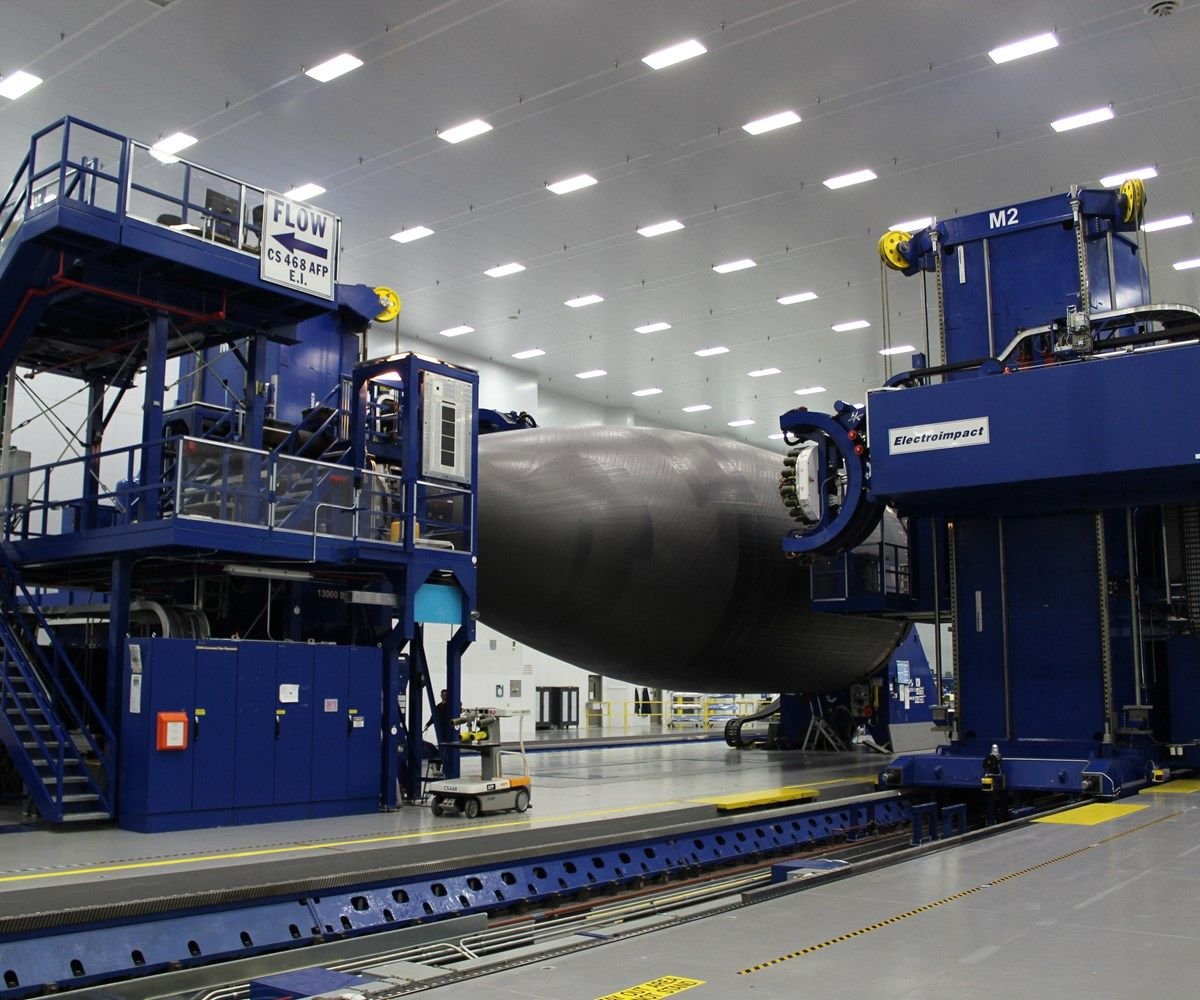
Local out-of-plane fiber waviness — often introduced during compaction of complex curved surfaces — dramatically reduces compression strength and buckling resistance. A 5° fiber misalignment can reduce compressive strength by 30–40%. This makes AFP (Automated Fiber Placement) process monitoring a critical quality control requirement.
Separation between laminate plies can be initiated by manufacturing (poor consolidation, contamination, incorrect cure cycle) or in-service impact. Delaminations are particularly dangerous in compression-loaded structure — they create unsupported sublaminates that buckle at loads far below the pristine design allowable. Post-impact compression strength (CAI) is a key certification test for aircraft CFRP structure.
Excess matrix material with insufficient fiber reinforcement produces areas of locally reduced stiffness and strength. In complex geometry components — corners, radius transitions, ply terminations — resin-rich zones are a common manufacturing challenge requiring process optimization and inspection validation.
Thermal Capability Spectrum: Matching Material to Mission
| Material System | Max Use Temp | Primary Application | Key Limitation |
|---|---|---|---|
| CFRP / Epoxy | ~150°C | Aircraft primary structure, fairings | Matrix Tg limits temp |
| CFRP / BMI | ~230°C | Military aircraft, engine nacelles | Higher cost, brittle |
| CFRP / Cyanate Ester | ~300°C | Spacecraft panels, radomes | Moisture sensitivity |
| CMC (SiC/SiC) | ~1,400°C | Turbine hot section, hypersonic TPS | Brittle, expensive |
| RCC | >2,000°C | Reentry leading edges, nose caps | Oxidizes without coating |
| Avcoat (Ablative) | ~2,700°C | Apollo, Orion heat shields | Single-use, no reusability |
| UHTC (ZrB₂, HfC) | >3,000°C | Next-gen hypersonic leading edges | TRL 3–5, brittle |
Emerging Technologies: The Next Generation of Aerospace Composites
CNT reinforcement of polymer and ceramic matrices offers theoretical specific strength improvements of 10–100×. Current challenges center on CNT alignment, dispersion, and interfacial bonding. Electrical conductivity improvements enable multifunctional structures with embedded sensing and lightning strike protection.
Microencapsulated healing agents embedded in the matrix release upon crack initiation, autonomously repairing microcracking before it propagates to delamination. Demonstrated healing efficiency of 75–90% for Mode I fracture toughness recovery. Potential to extend fatigue life and reduce inspection requirements in inaccessible structure.
Zirconium diboride (ZrB₂) and hafnium carbide (HfC) composites maintain structural integrity above 3,000°C with inherent oxidation resistance — unlike RCC, which requires protective coatings. Critical for reusable hypersonic leading edges and scramjet combustor structures where ablative and coated systems are inadequate.
What This Means for Aerospace Engineering Practice
Material selection is a systems engineering decision, not a materials decision. Choosing between CFRP, CMC, RCC, and ablatives requires simultaneous consideration of structural loads, thermal environment, reusability requirements, inspection access, manufacturing producibility, and cost — not just a materials property comparison. The engineer who selects Avcoat for a reusable hypersonic vehicle, or standard epoxy CFRP for a turbine hot section, has made a category error regardless of how well they know the material’s properties in isolation.
Damage tolerance drives certification. Every composite structural certification program — whether FAA Part 25 for commercial aircraft or NASA human-rating standards for spacecraft — centers on demonstrating that the structure can sustain defined damage (impact, delamination, environmental degradation) without catastrophic failure. The specific damage tolerance requirements differ by material system: CFRP structures must demonstrate residual strength after barely visible impact damage (BVID); CMC structures must demonstrate retained capability after defined fiber fracture; ablative systems must demonstrate adequate margin against unexpected recession modes. Columbia and Artemis I are both, fundamentally, damage tolerance failures.
Manufacturing process is structural design. A composite component’s realized properties are inseparable from how it was made. Fiber volume fraction, void content, ply waviness, cure cycle accuracy, and tooling dimensional control all enter the structural allowable as directly as fiber modulus or matrix strength. This is why aerospace composite manufacturing specifications are as rigorously controlled as material specifications — and why the structural engineer must understand manufacturing process, not just material properties.
Composite materials are no longer simply replacing metals in aerospace structures. They are enabling vehicle architectures — single-piece composite fuselage barrels, reusable ceramic hot structures, hypersonic vehicles that survive sustained Mach 10+ flight — that are physically impossible in conventional metallic alloys. As hypersonic vehicles and reusable spacecraft continue to evolve, advances in high-temperature composite materials and manufacturing technologies will likely become one of the most critical battlegrounds in aerospace engineering.
This aerospace composite materials guide provides an overview of the critical composite systems that are reshaping the aerospace industry.
htmlReady to Enroll?
NovaEd AeroLab — Spring II Classes Now Open
Aerospace STEM enrichment for kids Grades 1–8, taught by a working senior aerospace engineer with 30+ years of experience including human spaceflight. Real engineering. Real flight. Real fun.
📍 Orange
Starting Wed Apr 8
Level 1A Gr 1–3 · Wed 4:00–5:30
Level 2A Gr 4–7 · Wed 5:30–7:00
Level 3A Gr 8+ · Wed 7:00–8:30
📍 Corona
Starting Thu Apr 10
Level 1A Gr 1–3 · Thu 4:00–5:30
Level 2A Gr 4–7 · Thu 5:30–7:00
Level 3A Gr 8+ · Mon 5:30–7:00
Level 1C Gr 1–5 · Mon 4:00–5:30 ✦
Level 2C Gr 5+ · Mon 5:30–7:00
📍 Fontana
Starting Fri Apr 11
Level 1A Gr 1–3 · Fri 2:30–4:00
Level 2A Gr 4–7 · Fri 4:00–5:30