

The Boeing 737: How a “Baby Jet” Became the Most Structurally Durable Airframe in Commercial Aviation History
A deep technical examination of the engineering decisions, propulsion evolution, and structural philosophy that turned a near-cancellation into 11,000 deliveries.
At 13:15 PST on April 9, 1967, test pilots Brien Wygle and Lew Wallick rotated N73700 off Boeing Field’s Runway 13L, climbed to FL150, and pushed the throttles on two Pratt & Whitney JT8D-1 turbofans to sustain 400 mph indicated airspeed. Two and a half hours later, they touched down at Paine Field. What those two pilots flew that afternoon was not merely a new airplane — it was the first iteration of what would become the longest-running and highest-volume airframe program in commercial aviation history.
“I think they’ll be building this airplane when Bill Allen is in an old man’s home.”
— William M. Allen, President, Boeing Company, April 1967
Allen passed away in 1985. Fifty-nine years after that first flight, Boeing delivered its 11,000th 737. At any given moment on this planet, more than 500 of them are simultaneously airborne. This is not an accident of marketing. It is the result of deliberate, disciplined, and occasionally controversial engineering decisions made across four distinct design generations — decisions that aerospace engineers still study, debate, and learn from today.
The Original Constraint: Low Fuselage, Short Field, Tight Economics
The 737-100’s defining design constraint was one that no modern engineer would readily accept: a fuselage cross-section borrowed from the 707/727 family, with a floor-to-tarmac height of just 10 feet 4 inches. This was not aesthetics. Boeing’s airline customers needed ground servicing without specialized equipment at smaller regional airports.
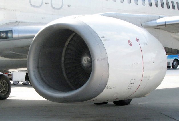
This constraint forced one of the most consequential decisions in the aircraft’s geometry: the engines had to be mounted under the wing, not aft like the 727, but hung so close to the ground that the nacelles are famously non-circular — flattened at the bottom to provide the necessary 17-inch minimum ground clearance. The JT8D turbofan’s accessory gearbox was relocated from the traditional 6 o’clock (bottom) position to the 4 o’clock position, directly influencing nacelle shaping and inlet geometry.
Original -100 Configuration: Key Structural Parameters
The fuselage shell uses a semi-monocoque construction with frames spaced at 20-inch intervals — a pitch inherited directly from the 707 program. Skin panels are primarily 2024-T3 aluminum (known for its superior fatigue crack growth resistance under tension cycling), while the upper wing covers transition to 7075-T6 for its higher compressive strength. This material pairing was not arbitrary; it reflected a mature understanding of the load environment each structural zone would experience across 20,000+ flight cycles over a 20-year service life — a DaDT philosophy that was state-of-the-art in 1967.
Four Generations: The Engineering Delta Across 59 Years
The 737 is often described as one airplane in four generations. Structurally and aeroelastically, that description is largely accurate. What changed across generations was not the fundamental fuselage barrel or wing attach philosophy — it was the propulsion system, the aerodynamic refinement, and increasingly, the avionics and flight control architecture.
| Generation | Variants | Engine | Key Structural / Aero Change | EIS |
|---|---|---|---|---|
| Original | -100, -200 | P&W JT8D | Baseline fuselage, 2-crew cockpit, slotted Fowler flaps | 1968 |
| Classic | -300, -400, -500 | CFM56-3 | EFIS cockpit, extended fuselage, winglets optional, revised nacelle inlet (flattened) | 1984 |
| Next Generation | -600, -700, -800, -900 | CFM56-7B | New wing (25% larger, increased sweep leading edge cuff, winglets), strengthened fuselage frames, fly-by-wire spoilers | 1997 |
| MAX | -7, -8, -9, -10 | CFM LEAP-1B | Advanced aluminum-lithium frames, composite tail cone, redesigned nacelle (MCAS introduced), split-tip winglets | 2017 |
The Classic’s Defining Challenge: CFM56 Integration
The transition from the JT8D to the CFM56-3 for the Classic generation (737-300/400/500) is arguably the single most instructive structural integration challenge in the program’s history — and the one that set the template for every subsequent nacelle modification.
The CFM56’s fan diameter of 60 inches (vs. the JT8D’s 49 inches) could not fit under the existing low wing without major structural rework. The engineering solution was a combination of: moving the engine forward and upward relative to the wing, reshaping the nacelle to an elliptical cross-section (flattened at the bottom), and relocating the accessory gearbox to the forward-top position. This produced the 737’s characteristic “chin” or bulged nacelle profile — not a compromise, but a deliberate structural and aerodynamic solution within a fixed fuselage-to-ground envelope.
The low-slung nacelle that defines the 737’s visual identity is not a legacy limitation. It is the geometric solution to an integration problem that Boeing’s structural and propulsion teams solved, in slightly different form, three times across four decades.
The NG Wing: A Structural Redesign Hiding Inside a Familiar Fuselage
The 737 Next Generation (NG) introduced what is functionally a new airplane from the wing box outward. The NG wing increased span from 94 feet to 112 feet 7 inches, boosted fuel capacity by over 30%, and incorporated a new leading edge cuff that improves low-speed handling and increases effective camber without requiring a new spar geometry.
Structurally, the NG wing uses a two-spar torque box design with machined aluminum alloy ribs, and the wing-to-fuselage interface — always a fatigue-critical location — was strengthened through a revised body-side fitting design that distributes bending loads more uniformly into the fuselage frames. The NG also introduced optional blended winglets (introduced initially on the -800), which reduce induced drag by approximately 5% but introduce new root bending moment loads that required rib and stringer reinforcement in the outer wing panel.
The MAX and MCAS: A Structural–Stability Interaction That Changed Aviation Certification
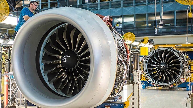
The 737 MAX introduced the CFM LEAP-1B engine, with a fan diameter of 68 inches — 8 inches larger than the CFM56-7B it replaced. Once again, the low-wing geometry forced the same nacelle-forward, nacelle-up solution used in the Classic. But the larger, heavier engine mounted further forward changed the aircraft’s pitch stability characteristics in a meaningful way.
To preserve commonality with the NG (and maintain the type rating that is central to airline economics), Boeing implemented the Maneuvering Characteristics Augmentation System (MCAS) — a software-based stability augmentation function embedded in the flight control computer. MCAS commanded automatic nose-down stabilizer trim under specific high-AoA, flaps-up conditions to counteract the aerodynamic pitch-up moment introduced by the repositioned nacelles.
From a structures and systems integration standpoint, MCAS is a reminder of a principle that experienced aerospace engineers know well: geometry changes propagate across disciplines. A nacelle moved 8 inches forward and upward to fit under a 1967-era fuselage created a stability delta that was addressed not in the structure, but in the software — and the interaction between that software, sensor redundancy architecture, and crew training ultimately led to two accidents, 346 fatalities, a 20-month global grounding, and the most consequential recertification effort in FAA history.
The MAX returned to service in November 2020 following MCAS redesign, enhanced redundancy (dual AoA sensor input), and comprehensive crew training requirements. The structural airframe was not the failure mode — but the program is now a permanent case study in system-level integration risk when incremental design changes are managed across a 50-year type certificate.
First flight of 737-100, Boeing Field. JT8D-1 engines, 2024/7075 Al structure, 93 ft wingspan.
737 Classic enters service with CFM56-3. Reshaped nacelle, EFIS cockpit, extended fuselage barrel.
737 NG EIS with redesigned wing (+25% area), strengthened fuselage frames, optional blended winglets. New production rate milestones.
737 MAX EIS. LEAP-1B engines, Al-Li structures, MCAS introduced. Peak of 52 aircraft/month production.
MAX grounded globally following Lion Air 610 and Ethiopian 302 accidents. MCAS redesign, recertification.
11,000th 737 delivered. More than 5,000 active in commercial service worldwide.
What the 737’s Longevity Actually Teaches Us
The popular narrative around the 737 is one of nostalgia and commercial triumph. From an engineering standpoint, the real lessons are more nuanced and more valuable:
1. Structural baseline decisions have multi-decade consequences. The 1960s-era fuselage diameter and floor height, chosen to meet short-field servicing requirements, directly constrained every engine integration decision from 1984 through 2017. The structural team that sized those frames never anticipated a 68-inch turbofan.
2. Fatigue life management is a living discipline. The 737’s service life has been extended multiple times through structural enhancement programs (SEPs) and via supplemental structural inspection documents (SSIDs). Aircraft built in 1988 are still flying in 2026 because Boeing and operators have maintained rigorous damage tolerance (DaDT) programs — not because the original structure was overbuilt, but because the inspection intervals and repair schemes have evolved with service data.
3. Type certificate continuity creates both efficiency and risk. The 737’s single type certificate spanning 59 years allowed airlines to qualify and train pilots at dramatically lower cost than a clean-sheet design. It also created incentive pressure to absorb aerodynamic and propulsion changes within the existing certification basis — pressure that, in the MAX program, contributed to consequences that reshaped FAA oversight philosophy entirely.
4. The best airframe programs aren’t defined by their first flight. N73700 — the original prototype, now “Fat Albert” in the Museum of Flight — was a proof of concept for a jet that nearly died in 1972 at 22 deliveries per year. The program survived because the underlying structural and aerodynamic architecture had room to grow. That adaptability — not the elegance of the original design — is the real engineering legacy of the 737.

Boeing is still building it. They will likely continue building it until at least the mid-2030s. Whether a successor emerges from the current new mid-market airplane studies or the 737 family simply grows a fifth generation, the engineering decisions made in Renton, Washington in 1964–1967 will continue to shape every flight taken by hundreds of millions of passengers every year.
Fifty-nine years. Eleven thousand airframes. One fuselage cross-section. That is what disciplined structural engineering, combined with the willingness to evolve, actually looks like at scale.
Ready to Enroll?
NovaEd AeroLab — Spring II Classes Now Open
Aerospace STEM enrichment for kids Grades 1–8, taught by a working senior aerospace engineer with 30+ years of experience including human spaceflight. Real engineering. Real flight. Real fun.
📍 Orange
Starting Wed Apr 8
Level 1A Gr 1–3 · Wed 4:00–5:30
Level 2A Gr 4–7 · Wed 5:30–7:00
Level 3A Gr 8+ · Wed 7:00–8:30
📍 Corona
Starting Thu Apr 10
Level 1A Gr 1–3 · Thu 4:00–5:30
Level 2A Gr 4–7 · Thu 5:30–7:00
Level 3A Gr 8+ · Mon 5:30–7:00
Level 1C Gr 1–5 · Mon 4:00–5:30 ✦
Level 2C Gr 5+ · Mon 5:30–7:00
📍 Fontana
Starting Fri Apr 11
Level 1A Gr 1–3 · Fri 2:30–4:00
Level 2A Gr 4–7 · Fri 4:00–5:30